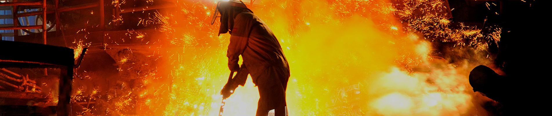
Auitzettingsvoeg in het textielEen flexibele verbindingsstuk wordt in industriële luchtkanalen geïnstalleerd om bewegingen tussen onderdelen van apparatuur of kanalen op te vangen. In plaats van thermische uitzetting, trillingen of uitlijningsveranderingen in stijve stalen constructies te forceren, vervormt het flexibele gedeelte mee met de beweging van het systeem.
Dilatatievoegen van textiel worden veelvuldig gebruikt in systemen voor het transport van hete lucht, uitlaatgassen, rookgassen en andere gasvormige procesmedia. Het flexibele element kan bestaan uit geweven technische stoffen, gecoate stoffen, gasdichtende membranen, verstevigingslagen en thermische isolatie, geselecteerd op basis van de specifieke bedrijfsomstandigheden.
Omdat het flexibele element niet-metaalachtig is, wordt dit type verbinding ook wel een ... genoemd.niet-metalen uitzettingsvoegofniet-metalen uitzettingsvoeg van textiel.
Voor industriële ontwerpen op maat, zie deBSTFLEX niet-metalen textiel expansievoeg.
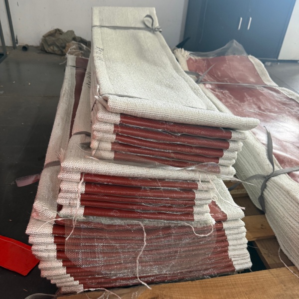
Een flexibele expansievoeg is een speciaal ontworpen, flexibel onderdeel dat tussen twee relatief stijve delen van een luchtkanalensysteem is geplaatst. Het doel ervan is om gecontroleerde beweging mogelijk te maken, terwijl de vereiste verbinding tussen die delen behouden blijft.
Industriële luchtkanalen behouden zelden hun afmetingen tijdens bedrijf. Wanneer een oven, ketel, uitlaatsysteem of proceskanaal opwarmt, zet de omringende metalen structuur uit. Bij afkoeling krimpt deze weer. Ventilatoren en roterende apparatuur kunnen ook trillingen veroorzaken, terwijl installatietoleranties kleine afwijkingen tussen aangrenzende componenten kunnen creëren.
Als deze bewegingen rechtstreeks via starre luchtkanalen worden doorgegeven, kunnen ze extra belastingen veroorzaken op:
De stoffen verbinding creëert een flexibele zone waarin een deel van die beweging kan plaatsvinden zonder dat de volledige kanaalconstructie zich als een star geheel hoeft te gedragen.
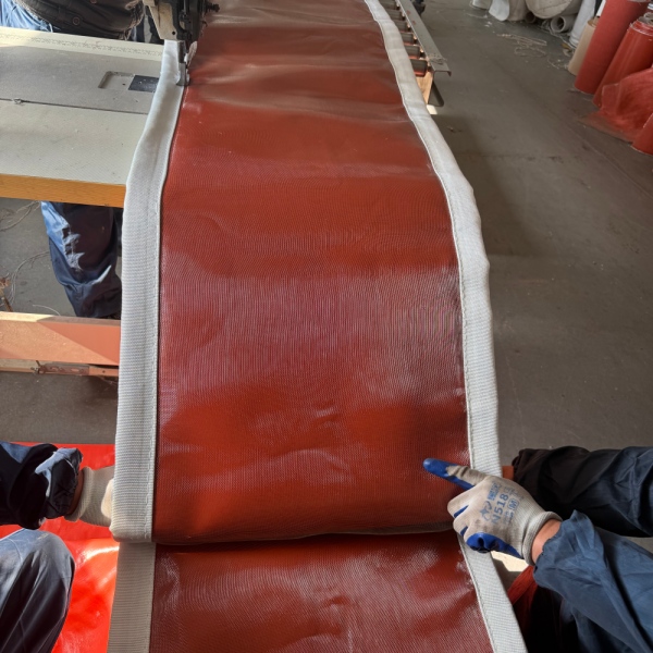
De termniet-metalen uitzettingsvoegDit beschrijft het flexibele element in plaats van elk afzonderlijk onderdeel van de complete constructie.
Rondom het scharnier kunnen nog steeds metalen frames, klemstangen, voeringen of andere onderdelen worden gebruikt. Het gedeelte dat de primaire flexibele beweging uitvoert, is echter vervaardigd van stof, elastomeer, gecoat textiel, gelamineerd membraan of een combinatie van deze materialen in plaats van een gevormde metalen balg.
Dit onderscheid is belangrijk omdat uitzettingsvoegen van textiel en metaal zich anders gedragen.
Een metalen balg vangt beweging op door de buigzaamheid van gevormde metalen plooien. Een stoffen expansievoeg maakt gebruik van de flexibiliteit van de textiele of composietband om van vorm te veranderen naarmate het kanaal beweegt.
Voor grote industriële leidingen, met name die leidingen die gasvormige media onder relatief lage druk transporteren, kan deze constructie aanzienlijke bewegingsvrijheid bieden in een compacte installatieruimte.
Het basiswerkingsprincipe is eenvoudig.
Stel je voor dat er twee delen van een heteluchtleiding zijn, gescheiden door een gecontroleerde opening. Een flexibel stoffen element overbrugt deze opening en is stevig bevestigd rondom de omtrek van elk leidingdeel.
Wanneer het luchtkanaal opwarmt en uitzet, verandert de afstand of uitlijning tussen de twee secties. In plaats van die beweging tegen te werken zoals een starre verbinding zou doen, verandert de flexibele band van vorm.
Afhankelijk van het ontwerp kan het gewricht op verschillende soorten bewegingen reageren.
Axiale compressie treedt op wanneer de afstand tussen de twee kanaalsecties langs de middellijn korter wordt.
Dit gebeurt vaak wanneer thermische uitzetting ervoor zorgt dat een deel van het luchtkanaal naar een ander deel toe beweegt. Het flexibele gedeelte wordt dan op gecontroleerde wijze samengedrukt of gevouwen om de kleinere afstand op te vangen.
Axiale verlenging is de tegenovergestelde situatie. De afstand tussen de verbindingsstukken neemt toe langs de lengteas.
Het textielelement moet voldoende beschikbare geometrie hebben om uit te rekken zonder te veel te worden uitgerekt.
Zijwaartse beweging treedt op wanneer een kanaalaansluiting ten opzichte van de andere zijdelings verschuift.
Dit is met name belangrijk in grote luchtkanalen, waar beweging van apparatuur, thermische uitzetting in een andere richting of de installatiegeometrie een verschuiving veroorzaakt in plaats van eenvoudige compressie of uitzetting.
Hoekbeweging treedt op wanneer de twee verbindende vlakken niet langer parallel zijn.
De flexibele band vervormt ongelijkmatig rondom de omtrek, waardoor de ene kant samengedrukt wordt terwijl een ander gedeelte uitzet.
Echte industriële systemen bewegen niet altijd slechts in één richting. Axiale, laterale en hoekverplaatsing kunnen gelijktijdig optreden.
Dit is een van de redenen waarom eenuitzettingsvoeg van textielkanaalDit is met name nuttig bij complexe leidingconfiguraties. De geometrie van de verbinding kan worden ontworpen op basis van de verwachte combinatie van bewegingen, in plaats van elke verplaatsing afzonderlijk te behandelen.
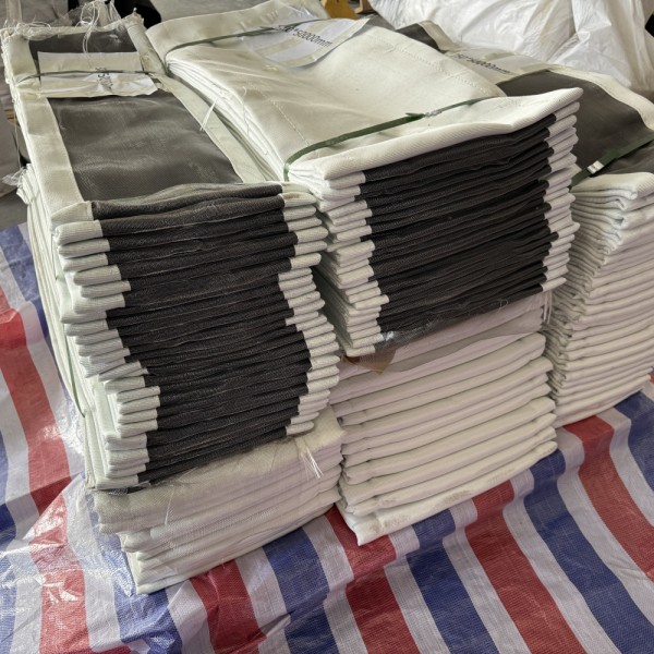
Thermische uitzetting is de bekendste reden voor het aanbrengen van een uitzettingsvoeg, maar het is niet de enige.
De volledige bewegingsbehoefte kan het gevolg zijn van diverse bedrijfsomstandigheden.
| Oorzaak | Wat gebeurt er in het systeem? | Rol van de uitzettingsvoeg |
|---|---|---|
| Thermische uitzetting | Metalen luchtkanalen zetten uit bij een temperatuurstijging. | Maakt gecontroleerde dimensionale beweging mogelijk. |
| Thermische krimp | Luchtkanalen krimpen tijdens stilstand of koeling. | Allows the system to return toward its cold position |
| Fan Vibration | Mechanical vibration is transferred from rotating equipment | Provides a flexible connection between equipment and ducting |
| Misalignment | Connecting duct faces may not be perfectly aligned | Can accommodate specified offsets within the joint design |
| Structural Movement | Supports or equipment may move relative to each other | Provides a controlled flexible section |
| Operating Cycles | Repeated heating and cooling creates cyclic movement | Accommodates repeated dimensional changes when correctly designed |
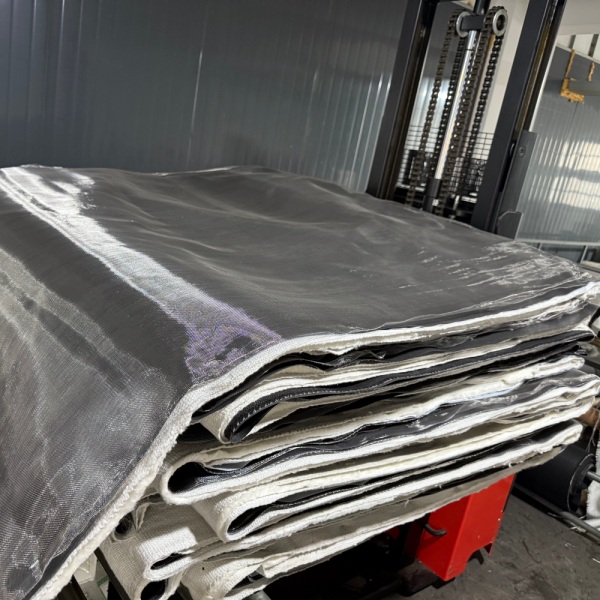
A fabric expansion joint should not be viewed simply as a piece of cloth connecting two ducts.
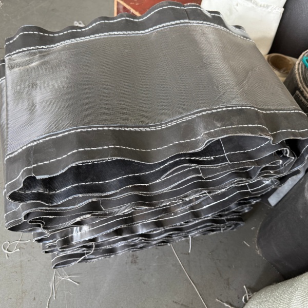
The flexible section is an engineered material system. Depending on service conditions, it may use a single flexible layer or several different layers, each selected for a specific function.
The outer layer forms part of the flexible envelope and may also provide resistance to weathering, environmental exposure or external mechanical conditions.
This layer helps contain the process gas. Its material must be compatible with the expected temperature, gas composition, moisture and chemical exposure.
Reinforcement provides mechanical support and dimensional stability to the flexible element. Fiberglass and other technical textile constructions are commonly considered depending on temperature and mechanical requirements.
High gas temperature does not necessarily mean every layer of an expansion joint should be exposed directly to that temperature.
An insulation package can reduce heat transfer from the process side toward temperature-sensitive sealing or outer layers.
Hot gas velocity, ash, dust or abrasive particles can damage an unprotected flexible surface. Some systems therefore require an internal liner, baffle or other protection to shield the joint from direct gas flow and particulate impact.
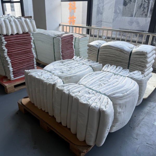
One material rarely provides every property required by a severe industrial application.
For example, a material with excellent temperature resistance may not provide the best gas sealing. A highly flexible sealing material may require reinforcement. A chemically resistant membrane may need insulation to keep its operating temperature within an acceptable range.
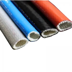
As a result, manyfabric expansion jointsuse a combination of materials rather than one fabric performing every function.
Typical material families include:
BSTFLEX also manufactures a broad range ofhigh temperature fabrics, allowing material construction to be evaluated according to thermal, chemical and mechanical requirements.
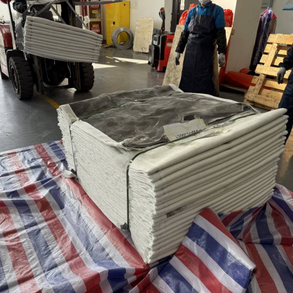
Fabric joints are mainly associated with industrial gas-handling and ducting systems rather than conventional high-pressure liquid piping.
Typical applications include the following.
Boilers, furnaces and combustion equipment can generate hot flue gases that must travel through large duct networks. These ducts experience significant dimensional change between ambient and operating temperatures.
Exhaust ducts connected to engines, industrial furnaces, thermal processing equipment or pollution-control systems may require movement compensation between hot equipment and downstream ducting.
Power plants use large gas-handling systems around boilers, fans, air-handling equipment and emission-control installations. Thermal growth and vibration can occur at multiple connection points.
Cement production combines heat, large duct dimensions, dust and continuous process operation. Flexible expansion sections may be required around kiln-related systems, fans and process ducts.
High-temperature furnaces, hot-air systems and exhaust ducts in steel and metal-processing plants can generate significant thermal movement.
Placing a flexible connection between rotating equipment and rigid ducting can help prevent all equipment movement from being transmitted directly into the surrounding duct structure.
Large ducting systems used with filtration, scrubber, flue-gas treatment and other air-pollution-control equipment often need flexible connections between process components.
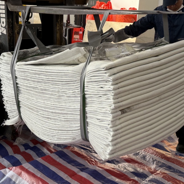
Both products are intended to manage movement, but they should not be considered interchangeable simply because they share the term “expansion joint.”
| Characteristic | Fabric Expansion Joint | Metallic Bellows |
|---|---|---|
| Flexible Element | Fabric, coated textile or composite membrane | Formed metal bellows |
| Common Application | Large industrial ducts and gaseous-media systems | Industrial piping and engineered duct or process systems |
| Movement Method | Flexible belt changes geometry | Metal convolutions flex |
| Large Duct Sizes | Well suited to custom large cross-sections | Requires application-specific metallic design |
| Multidirectional Movement | Can accommodate several movement directions in one flexible section | Depends on bellows geometry and assembly design |
| Material System | Can combine several fabric, coating and insulation layers | Primarily determined by metallic alloy and bellows construction |
Pressure, temperature, process medium, movement, duct size and system design must all be considered before deciding which expansion joint technology is appropriate.
A flexible joint can help isolate vibration between connected components because its flexible element does not behave like a completely rigid metal duct section.
This is useful near fans, blowers and other equipment that produces mechanical vibration.
However, vibration should still be treated as an engineering input. Frequency, amplitude, equipment arrangement and joint geometry all influence performance. A fabric expansion joint should not be selected only because a system is described as “vibrating.”
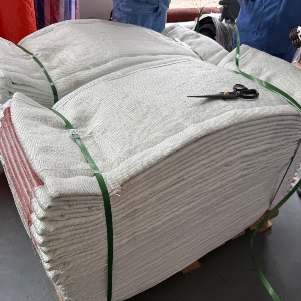
There is no universal movement value that applies to every fabric expansion joint.
Movement capability depends on:
For this reason, axial, lateral and angular movements should be stated separately when specifying a custom expansion joint.
A request such as “50 mm total movement” is less useful than specifying how that movement occurs.
For example:
These values are examples of how movement information can be communicated, not standard ratings for every joint.
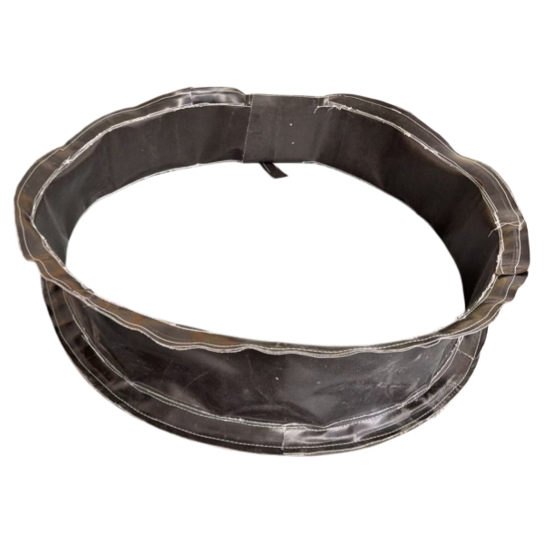
There is also no single temperature rating that defines all fabric expansion joints.
The allowable process temperature depends on the complete construction.
A high-temperature joint may be designed so that the process-side protection and insulation reduce the temperature reaching the gas-sealing membrane and external flexible layers.
Temperature selection should therefore consider:
This is why specifying only “high temperature fabric expansion joint” is insufficient for engineering selection.
A manufacturer needs more than the nominal duct dimensions to select a reliable construction.
The most useful project information includes:
| Design Information | Typical Details Required |
|---|---|
| Duct Geometry | Round, rectangular, square or special shape |
| Dimensions | Diameter or width and height |
| Face-to-Face Length | Available installation distance |
| Temperature | Normal and maximum process temperature |
| Pressure | Positive or negative operating and design pressure |
| Process Medium | Hot air, flue gas, exhaust gas or other process gas |
| Axial Movement | Compression and extension |
| Lateral Movement | Required transverse offset |
| Angular Movement | Required angular displacement |
| Chemical Conditions | Acidic, alkaline, moisture or other process exposure |
| Particulate Loading | Dust, ash or abrasive particles |
| Installation Environment | Indoor, outdoor, weather exposure or confined area |
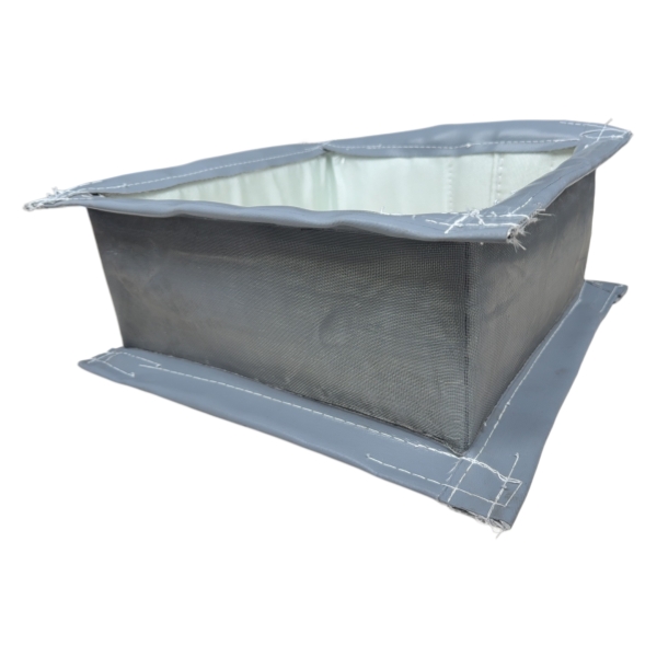
Anon metallic expansion jointshould be considered when an industrial ducting system needs flexibility and the operating conditions are suitable for a fabric-based construction.
Typical reasons include:
The final decision should always be based on actual system conditions rather than the product name alone.
Some basic constructions can be standardized, but industrialfabric expansion jointsare frequently customized.
Two ducts with the same dimensions may require completely different expansion joints if they operate at different temperatures, carry different gases or experience different movements.
Important differences may include:
This is why drawings and operating data are particularly valuable when sourcing replacement or OEM fabric expansion joints.
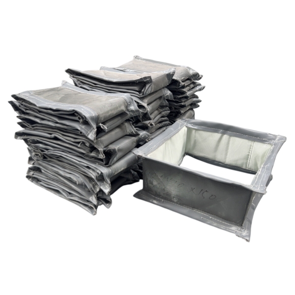
Rectangular joints are widely used on large industrial duct systems. Their corner sections require careful design because the flexible element does not deform identically along straight sides and corners.
Round joints are used on circular ducting, fan connections and exhaust systems. The circumference provides a continuous attachment surface around the duct.
Square configurations are similar in principle to rectangular designs but may be required by specific duct or equipment layouts.
Transitions, non-standard dimensions and application-specific geometries can be manufactured when existing industrial equipment cannot accept a standard shape.
Expansion joint service life depends heavily on correct specification and installation.
Potential failure mechanisms include:
A damaged joint should therefore not automatically be replaced with an identical copy without understanding why the original unit failed.
For replacement projects, operating history can be as valuable as dimensional information.
In industrial ducting, the terms are often used for closely related products. A fabric expansion joint uses a flexible non-metallic fabric or composite element, so it falls within the broader non-metallic expansion joint category. The exact terminology varies by industry and construction.
It provides a flexible connection between sections of industrial ductwork so thermal expansion, contraction, lateral displacement, angular movement, vibration and specified misalignment can be accommodated without making the connection completely rigid.
Typical locations include industrial exhaust ducts, flue-gas systems, furnace and boiler ductwork, fan connections, cement plants, power-generation equipment, steel-processing facilities and air-pollution-control systems.
Yes. Depending on the design, they can accommodate axial compression, axial extension, lateral movement, angular movement and combinations of these movements.
No. Fiberglass is an important reinforcement and high-temperature textile, but complete expansion joints may combine coated fiberglass, PTFE-coated fabric, silicone-coated textiles, silica fabrics, insulation and other materials according to operating conditions.
Ja, mits het complete materiaalsysteem is ontworpen voor de daadwerkelijke procestemperatuur en gasomstandigheden. Toepassingen bij hoge temperaturen vereisen vaak meerdere functionele lagen en een adequate bescherming tussen de hete gasstroom en het flexibele afdichtingselement.
Niet automatisch. Dilatatievoegen van textiel en metaal hebben verschillende druk-, bewegings-, temperatuur- en mechanische eigenschappen. De systeemomstandigheden moeten worden geëvalueerd voordat de technologie van de dilatatievoegen wordt gewijzigd.
Nuttige informatie omvat de breedte en hoogte of diameter van het kanaal, de lengte tussen de flensvlakken, de flensafmetingen, de boutconfiguratie, de vorm van de verbinding en de beschikbare installatieruimte. Ook de bedrijfstemperatuur, -druk, het medium en de bewegingsvereisten zijn essentieel.
BSTFLEX ontwikkeltuitzettingsvoegen van textielVoor industriële kanaal-, uitlaat-, hetelucht- en rookgastoepassingen. De constructie kan worden aangepast aan ronde, rechthoekige, vierkante en niet-standaard kanaalvormen, waarbij de materiaalkeuze afhangt van de temperatuur, druk, procesmedia, beweging en installatieomstandigheden.
Als u een nieuw systeem ontwikkelt of een bestaande verbinding vervangt, bekijk dan de volgende informatie.BSTFLEX niet-metalen textiel expansievoegProductpagina voor beschikbare constructie- en aanpassingsopties.
Voor een technische beoordeling verzoeken wij u de afmetingen van uw luchtkanalen, de normale en maximale temperatuur, de werkdruk, het procesmedium, de axiale beweging, de laterale beweging, de installatielengte, de hoeveelheid en de beschikbare tekeningen door te sturen.
Vraag een offerte aan voor een op maat gemaakte uitzettingsvoeg van textiel

 English
 français
 Deutsch
 русский
 italiano
 español
 português
 العربية
 日本語
日本語 한국의
한국의 Türkçe
 Polski
 Tiếng Việt
 slovenský
 Indonesia